


Description
Tk3-2E Operation instruction
Scope of Application
Suitable for Bentley-Nevada series 7200 and 3300 probes with diameters of 5mm, 8mm, 11mm,
Verification of 14mm and another non-contact eddy current axial vibration and axial displacement detection probes.
The Purpose
To improve the operation skills of the staff, all staff can correctly use the TK3-2E vibration and displacement probe calibration.
Personnel qualification, number of personnel and division of responsibilities
Qualification and quantity of personnel
Understand the structure and working principle of TK3-2E, and be familiar with the equipment operation specifications and safety precautions
Fixed fault discrimination ability, can deal with the abnormal condition of equipment in time.
Before the operation, the division of labor should be coordinated. Generally, there should be 2-3 persons to carry out the work, 1 person to operate, and other personnel to cooperate with the record number
According to the information, the cooperating personnel should be familiar with tK3-2E precautions, obey the arrangement of equipment operators, and do at the same time
Good care.
Division of Responsibilities
The workshop technical group is the competent department of this work instruction, responsible for the technical guidance and supervision of the work.
Check.
Each shift shall strictly implement the operation technical requirements and the corresponding production safety ban during the operation.
Equipment preparation and requirements
Make sure tK3-2E is intact before the operation and within the limited period of calibration (general calibration micrometer).
Select the appropriate probe clamp according to the size of the calibrated probe.
Select the matching preamplifier according to the probe type.
The digital voltmeter used for measuring voltage must be checked within the valid time of identification. 5 Items must be checked before operation
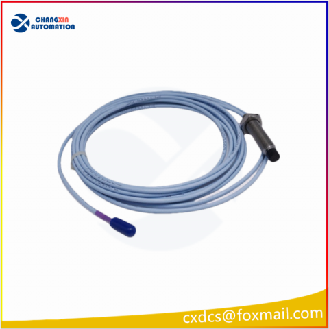
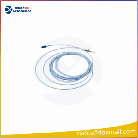
Check that the probe and component cable assembly is intact, the joint has no oxidation corrosion, and the protective layer at the end should not be used
There are bruising or peeling marks.
Check the integrity of the extension cable, no short circuit, no open circuit, no oxidation corrosion of the joint, and no damage to the protective layer.
Make sure that the probe and extension cable is installed, and connect the power cord after checking correctly, and make sure that the power switch is disconnected
Make sure the output voltage of the power supply and the positive and negative connection of the power line of the preheater are correct before closing the power switch.
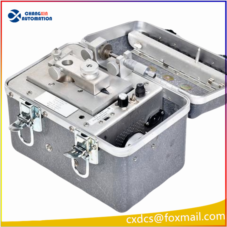
Step of shaft displacement probe calibration
Connect the displacement probe to the extension cable as shown in the figure below, and connect the other end of the extension cable to the front-end loader.
Fix the probe on the probe seat with an appropriate probe clamp so that the probe top touches the calibration target.
As shown in the figure above, the front-end power end (-24V DC) and the COMMON end (-24V DC) are connected to the -24V DC power supply. Please pay attention to this
Do not close the power switch.
The common end and output end of the preprocessor are connected to the digital voltmeter. The digital voltmeter used for measurement must be within the validity period of identification
Inside.
After checking everything is correct, close the power switch and send 24V DC to the power end and common end of the preprocessor.
Adjust the screw micrometer on the TK3-2E calibrator to align the indicating number at 0mm, and then set the indicating value of the micrometer
Increase to 0.25mm, record the voltage value of the digital voltmeter, at this point is the output voltage of the preprocessor,(pay attention to the thousandths
The scale of the ruler, if the scale is in inches then a small square is converted to 0.025mm).
Increase the clearance at a value of 0.25mm each time until the indicated value is 2.5mm, and record the output power for each time
Pressure value (checkpoint not less than 10 points)

Description
The TK-3 Proximity System Test Kit simulates shaft vibration and position for calibrating Bently Nevada monitors. It verifies
the operating condition of the monitor readouts as well as the condition of the proximity transducer system. A properly
calibrated system ensures that the transducer inputs and the resulting monitor readings are accurate.
The TK-3 uses a removable spindle micrometer assembly to check the transducer system and position monitor
calibration. This assembly features a universal probe mount that will accommodate probe diameters from 5 mm to 19
mm (0.197 in to 0.75 in). The mount holds the probe while the user moves the target toward or away from the probe tip in
calibrated increments and records the output from the Proximitor Sensor using a voltmeter. The spindle micrometer assembly also features a convenient magnetic base for ease of use in the field. Vibration monitors are calibrated using the motor-driven wobble plate. A swing-arm assembly located over the wobble plate holds the proximity probe in place. This
assembly uses a universal probe mount, identical to that used with the spindle micrometer assembly. By using the absolute scale factor of the proximity probe in conjunction
with a multimeter, the user adjusts the probe to find a position where the desired amount of mechanical vibration
(as determined by peak-to-peak DC voltage output) is present. No oscilloscope is needed.
The user can then compare a vibration monitor’s reading to the known mechanical vibration signal input viewed by the proximity probe. The mechanical vibration signal from the TK-3 can range from 50 to 254 μm (2 to 10 mils) peak-to peak.
Our Recommend
| GE Bently Nevada | 3500/94-15-01-02 |
| GE Bently Nevada | 3500/94-15-02-02 |
| GE Bently Nevada | 3500/94-15-03-02 |
| GE Bently Nevada | 3500/93-01-00-00-00 |
| GE Bently Nevada | 3500/93-01-01-00-00 |
| GE Bently Nevada | 3500/93-01-02-00-00 |
| GE Bently Nevada | 3500/93-01-03-00-00 |
| GE Bently Nevada | 3500/93-01-04-00-00 |
| GE Bently Nevada | 3500/93-01-05-00-00 |
| GE Bently Nevada | 3500/93-02-00-00-00 |
| GE Bently Nevada | 3500/93-02-01-00-00 |
| A-B Allen Bradley | 1746SC-IA8I |
| A-B Allen Bradley | 1746SC-IN04VI |
| A-B Allen Bradley | 1746SC-INI4VI |
| A-B Allen Bradley | 1746SC-INO4I |
| HONEYWELL | MC-TDIY22 |
| HONEYWELL | MC-TDOY22 |
| HONEYWELL | MC-TSIM12 |
| HONEYWELL | MU-FOED02 |
| HONEYWELL | TC-PRR021 |
| ABB | DSQC609 |
| ABB | DSQC609 3HAC14178-1 |
| ABB | DSQC611 |
| ABB | DSQC625 3HAC020464-001 |
| ABB | DSQC626A 3HAC026289-001 |
| ABB | DSQC627 3HAC020466-001 |
| ABB | DSQC633 3HAC022286-001 |


There are no reviews yet.