


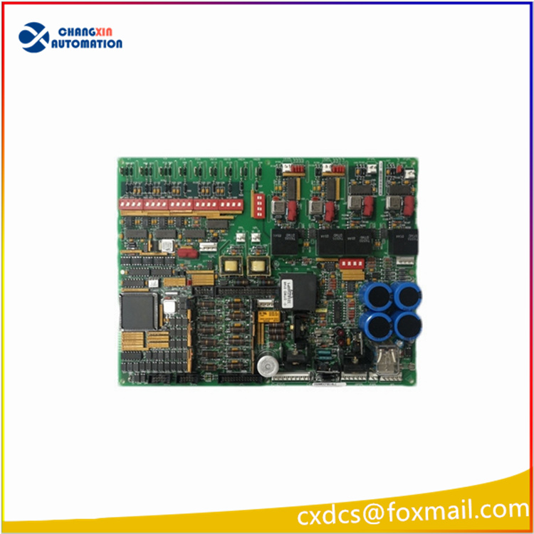
Product Introduction
The DS200DCFBG1B Power Supply Board (DCFB) receives 38 and 115 V ac (24 V dc) input power from the control power transformer (CPT), and provides control-level power to the drive and 115 V ac power (NA) to the enclosure fans.
Technical Specifications
| Manufacture | General Electric(GE) |
| Model | DS200DCFBG1BPC |
| Part Number | DS200DCFBG1B |
| Description | POWER SUPPLY BOARD |
| Origin | USA |
| Dimension | 32*24*5cm |
| Weight | 0.75kg |
Product Details
The DS200DCFBG1B board is used in DC2000, CB2000,EX2000, FC2000, GF2000, ME2000, and AC2000 IGBT drive applications. The EX2000 uses the board for a different purpose than a drive does. When the information is different for the EX2000 applications, it is shown in italics in parentheses (NA = Not Applicable).
The DCFB board includes the following circuits:
• Control-level power supplies (+5, ±15, and ±24 V dc)
• Motor field power circuits (except the SCR module)
• Driver circuits for the motor field SCR gate pulse generators
• Circuits to monitor numerous AC line and DC motor signals, including:
− Armature current(s) and voltage(s) (NA)
− Motor field currents (NA)
− AC line current
− AC line voltage magnitude and phase sequence
POWER SUPPLIES:
The DS200DCFBG1BPC board receives 38 V ac (±10%) from the CPT (24 V dc). This voltage is full-wave rectified and filtered to produce the unregulated ±24 V dc outputs. The +24 V DC output is rated at 3 A, and the 24 V DC output is rated at 1 A.
Regulators on the DS200DCFB board derive ±15 V dc from the ±24 V dc supplies. The ±15 V dc outputs are each rated at 0.8 A, of which 0.25 A is available for external loading.
The DCFB board also generates a +5 V dc, 4 A output from the +24 V dc supply. The /PSEN signal on 2PL goes to a TTL low state when the +5 V dc supply is in regulation, and the signal goes high if the +5 V dc supply goes out of regulation. When high, /PSEN generates a microprocessor reset on the Drive Control Card (SDCC/LDCC).
The DCFB board provides isolated +5 and ±15 V DC supplies to power the armature current feedback circuits.
The power supply outputs are protected against short circuits by fuses FU2 and FU3 (7 A, 2AG). Light-emitting diodes (LEDs) CR51 and CR55 provide blown fuse indication for these fuses. The 115 V AC output is protected by fuse FU1 (1/2 A, 2AG). Neon light LT1 provides blown fuse indication for FU1.
VOLTAGE AND CURRENT FEEDBACK VCO CIRCUITS:
The DCFB board includes voltage-controlled oscillator (VCO) circuits that convert input voltages to frequency signals. Each VCO has a nominal output frequency of 250kHz. The output frequency varies from 0 to 500 kHz, depending on the input voltage. VCO outputs are sent to the SDCC/LDCC board through connector 1PL to provide feedback of the following:
• SCR bridge ac input voltage
• Output bridge voltage
• Motor voltage (NA)
• Millivolt signals from field shunts
• Millivolt signals from armature shunts
The output bridge VCO circuit provides feedback to the SDCC/LDCC board through connector 1PL, pin 13 (1PL-13). DIP switch SW4 is used to scale the voltage applied to the circuit. A frequency-to-voltage reconstruction circuit provides a diagnostic signal for testpoint TP37 on the SDCC/LDCC board through 1PL-37. The diagnostic bridge voltage signal can be viewed using an ac-coupled oscilloscope. The second VCO provides feedback of the motor voltage to the SDCC/LDCC board through 1PL-39.DIP switch SW5 is used to scale the voltage applied to the circuit.


There are no reviews yet.