

")

Technical Specifications
| Manufacture | General Electric(GE) |
| Model | DS200DCFBG2BNC |
| Part Number | DS200DCFBG2BNC |
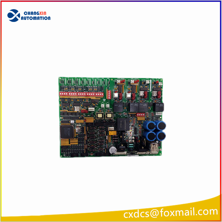
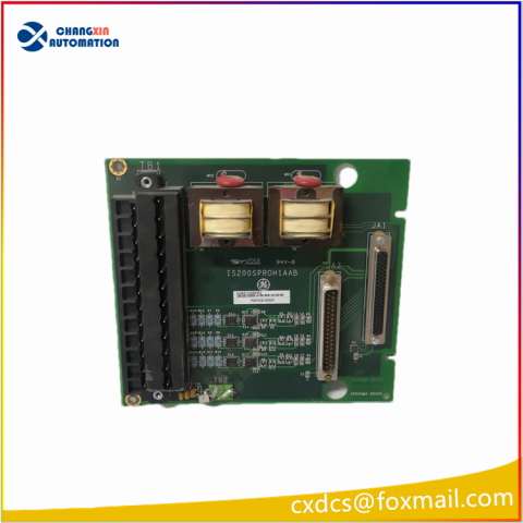
| Description | POWER SUPPLY BOARD |
| Origin | USA |
| Dimension | 32*24*5cm |
| Weight | 0.75kg |
Product Details
The DS200DCFBG2BNC board includes a motor voltage attenuation circuit that provides an analog representation of the motor voltage. This signal is sent to the SDCC/LDCC board through 1PL-6. The attenuation circuit is biased at 2.5 V, and can vary from 0 to 5 V depending on the motor voltage. DIP switch SW6 is used to scale the motor voltage feedback.
The DCFB board contains amplifier circuits that process the AC line-to-line voltages. The voltage feedback signals are sent to the SDCC/LDCC board through 1PL-11, 1PL-12, and 1PL-29. These signals are used to detect power bridge SCR failures and may also be used to derive the synchronization signal for the firing of the SCRs. DIP switches SW1, SW2, and SW3 are used to scale the AC line voltage feedback.
Sample Board Part Number, DS Series:
|
DS
|
Identifies GE Industrial Control Systems.
|
| -200 |
Indicates that the board does not contain firmware. (215 indicates the board contains firmware and/or other components added to the base level board.)
|
| -DCFB |
Board functional acronym.
|
| -G |
A group, or variation, of a particular board.
|
| -A |
A board revision (functional change) that is not backward compatible.Essentially a new catalog number.
|
| -A |
A board revision (functional change) that is backward compatible.
|
| -A |
A board revision (artwork change) that is backward compatible.
|
EE PARAMETER ADJUSTMENT
After installing a new DS200DCFBG2BNC board, the EE parameter for voltage feedback offset, EE.574 (VFBOFS), must be adjusted. The procedure for performing this adjustment varies with the application of the board and the tools that are available (programmer board, ST2000, GE Control System Toolbox, or LynxOS Configurator).
The DS200DCFBG2BNC board is used in DC2000, CB2000, EX2000,FC2000, GF2000, ME2000, and AC2000 IGBT drive applications. Refer to the applicable drive instruction book for performing the EE parameter adjustment procedure, if applicable.
This equipment contains a potential hazard of electric shock or burn. Only adequately trained persons who are thoroughly familiar with the equipment and the instructions should install or maintain this equipment.
BOARD IDENTIFICATION
A printed wiring board is identified by an alphanumeric part (catalog) number stamped on its edge. For example, the Power Supply Board is identified by part number DS200DCFBG#ruu.
WARRANTY TERMS
The GE Industrial Control Systems Terms and Conditions brochure details product warranty information, including the warranty period and parts and service coverage.
The brochure is included with customer documentation. It may be obtained separately from the nearest GE Sales Office or authorized GE Sales Representative.
WARRANTY PARTS AND SERVICE
Fuses FU1, FU2, and FU3 are the only end-user replaceable components on the DCFB board. If any other components on the board fail, the board needs to be replaced as a unit.
To obtain a replacement board or service assistance, contact the nearest GE Service Office.
Please have the following information ready to exactly identify the part and application:
• GE requisition or shop order number
• Equipment serial number and model number
• Board number and description

There are no reviews yet.