


FUNCTIONAL DESCRIPTION:
IS200TBCIH1C is a Contact Input Terminal Board manufactured by General Electric as part of the Mark VI Series used in gas turbine control systems. 24 dry contact inputs are supported by the contact input terminal board, and they are wired to two barrier-type terminal blocks. To excite the contacts, TBCI is linked with dc electricity. For surge and high-frequency noise protection, noise suppression circuitry is present at the contact inputs.
MARK VI SYSTEMS:
The terminal board of the Mark VI system is connected to the VME rack housing the VCCC or VCRC processor board by cables with molded connections. Systems in both simplex and TMR are supported. The TBCIH1B and TBCIH2B boards are identical to the TBCIH1C and TBCIH2C boards in terms of functionality and are compatible with Mark VI.
MARK VIe SYSTEMS:
The PDIA I/O packets in the Mark VIe system plug into the TBCI. A range of system configurations is supported by one, two, or three PDIA packs. For connector JT1 to be correctly mechanically aligned with the mechanical support of the I/O pack in Mark VIe, this board must be in the C version.
INSTALLATION:
- Power down the VME processor rack
- Slide in the VTCC board and push the top and bottom levers in with your hands to seat its edge connectors
- Tighten the captive screws at the top and bottom of the front panel
- BOARD VERSIONS:


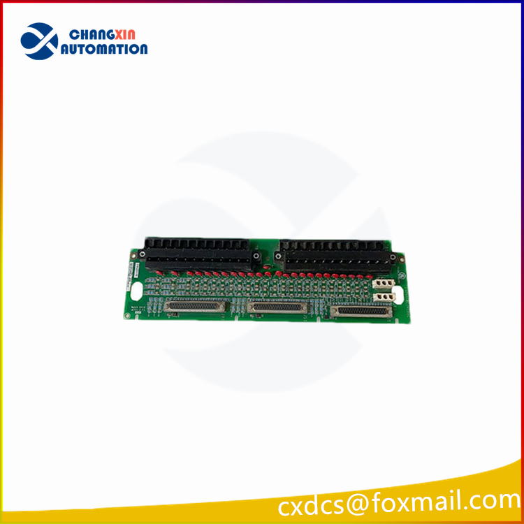
Fig 1: TBCI Contact Input Terminal Board
INSTALLATION:
WIRING:
The two I/O terminal blocks installed on the terminal board are directly linked to the 24 dry contact inputs. Two screws hold these blocks in place, and they can be unplugged from the board for upkeep. Each block has 24 terminals that can accommodate wires up to #12 AWG. Directly to the left of each terminal block is a shield terminal strip connected to the chassis ground.
POWER CONNECTION:
As depicted in the following figure, the excitation voltage is wired in through plugs JE1 and JE2.
CABLING CONNECTIONS:
JR1 is used for simplex systems, and all three connectors are utilized for TMR systems. Depending on the type of Mark VI or Mark VIe system and the level of redundancy, cables or I/O packs are plugged in.

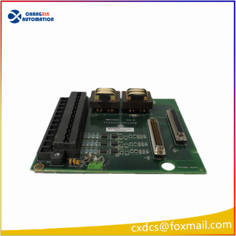
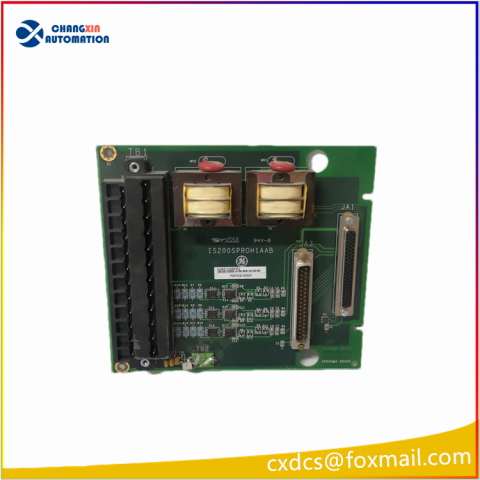
Fig 2: TBCIH1C Terminal Board Wiring and Cabling
OPERATION:
Near each input’s point of signal entry, filters decrease high-frequency noise and prevent surges. From a floating 125 V dc (100-145 V dc) supply from the turbine control, the dry contact inputs on H1 receive their power. Each contact input is fed after the 125 V dc bus has been current restricted in the power distribution module. The specification table indicates that the H2 and H3 variants use lower voltages.
The system controller receives the discrete input voltage signals from the I/O processor, which then passes them to optical isolators for group isolation. In isolation circuits, the reference voltage establishes a transition threshold that is equal to 50% of the applied floating power supply voltage. When the voltage drops below this threshold, all contacts are required to display open, thus the tracking is clamped to go no lower than 13 percent of the nominal rated supply voltage.

Fig 3: Contact Input Circuits
Each input has two terminal points, one of which (a screw) serves as the positive dc source and the other of which (an input) serves as the return to the board. The first 21 inputs on each terminal board have a current loading of 2.5 mA per point, while the final three have a 10 mA loading to facilitate interfacing with external solid-state output devices. Designed for NEMA Class G creepage and clearance is the contact input circuitry.
DIAGNOSTICS:
- One is monitoring the excitation voltage. The I/O pack/board sets and latches a diagnostic warning if the excitation falls under 40% of the nominal voltage.
- To test the terminal board, all inputs are compelled to the open contact (fail-safe) state. Any input that does not pass the diagnostic test is put into the failsafe state, which causes a fault to be created.
- A fault is issued if the input from this board does not match the TMR voted value from all three boards.
- The I/O pack or board interrogates each terminal board connector’s unique ID device. A read-only chip that also contains the board’s serial number, board type, revision number, and the location of the JR1/JS1/JT1 connectors is coded with the connector ID. A hardware incompatibility fault is triggered when the controller reads the chip and a mismatch is found.


There are no reviews yet.