


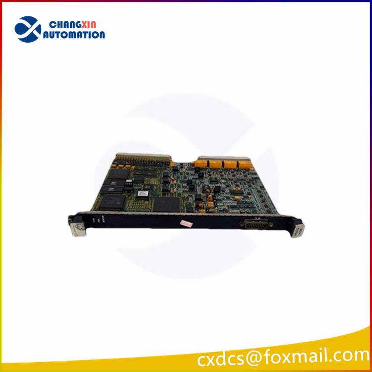
Functional Description
IS200VSVOH1BED is a servo control board developed by GE. It is a part of Mark VI control system. The Servo Control (VSVO) board plays a pivotal role in the precise control of four electro-hydraulic servo valves responsible for actuating the steam/fuel valves within the system. These valves are instrumental in regulating the flow of steam or fuel, ensuring optimal performance and efficiency in industrial processes. The VSVO board orchestrates the operation of these servo valves, employing sophisticated control algorithms to maintain precise control over valve positioning and fluid flow rates.
Features
- The four channels controlled by the board are typically allocated between two servo terminal boards, namely TSVO or DSVO. This distribution allows for efficient management of servo valve operations, ensuring redundancy and reliability in critical applications. Each terminal board interfaces with the servo valves, providing essential control signals and feedback mechanisms to the board.
- Valve position feedback is crucial for maintaining accurate control over the servo valves. Linear variable differential transformers (LVDTs) are employed to measure the precise position of the valves, providing real-time feedback to the VSVO board. This feedback mechanism allows the control algorithms to adjust valve positions dynamically, ensuring optimal performance under varying operating conditions.
- Three cables connect via the J5 plug on the front panel and the J3/J4 connectors on the VME rack. These cables facilitate communication and power supply to the VSVO board, enabling seamless integration into the system architecture. The terminal board provides simplex signals through the JR1 connector, while also distributing TMR (Triple Modular Redundancy) signals to the JR1, JS1, and JT1 connectors. Additionally, plugs JD1 or JD2 serve as interfaces for external trips from the protection module, allowing for immediate shutdown in case of critical faults or emergencies.
Installation
- Power Down the VME Processor Rack: Before proceeding with the installation, it is crucial to power down the VME processor rack. This step ensures safety and prevents any potential damage to the board or the system components. Follow the manufacturer’s guidelines for safely shutting down the rack to avoid any unforeseen issues.
- Slide in the Board and Seat Edge Connectors: Carefully slide the V-type board into the designated slot on the VME processor rack. Ensure that the board aligns properly with the slot guides to prevent any misalignment. Once the board is positioned correctly, use your hands to push the top and bottom levers inward. This action helps to seat the edge connectors securely into their corresponding slots on the rack.
- Tighten Captive Screws at the Top and Bottom of the Front Panel: With the board properly seated, locate the captive screws located at the top and bottom of the front panel. Use a suitable tool to tighten these screws securely. Ensure that the screws are tightened adequately to provide firm support and stability to the installed board. However, exercise caution not to overtighten the screws to avoid damaging the board or the rack enclosure.
Fault detection
Fault detection mechanisms for suicide servo outputs are crucial for maintaining system integrity and preventing potential hazards. These mechanisms are designed to detect anomalous conditions that may compromise the operation of the servo system. Two primary triggers for initiating suicide servo outputs include:
- Servo Current Out of Limits or Not Responding: Detection of servo currents exceeding predefined limits or failing to respond appropriately triggers the initiation of suicide servo outputs. Servo currents provide vital feedback on the performance and operation of the servo system. When currents deviate from expected levels or exhibit erratic behavior, it indicates potential issues with the servo mechanisms or associated control circuits. Initiating suicide servo outputs in such scenarios helps mitigate risks and prevent further damage to the system components.
- Regulator Feedback Signal Out of Limits: Anomalies in the regulator feedback signal, such as deviations from predefined limits, trigger the activation of suicide servo outputs. The regulator feedback signal plays a crucial role in regulating the operation of the servo system, ensuring precise control and stability. Any discrepancies or abnormalities in this signal indicate potential malfunctions or disturbances in the feedback loop. By initiating suicide servo outputs in response to such anomalies, the system can promptly address the underlying issues and prevent adverse consequences.

There are no reviews yet.