


I. Basic Material Information
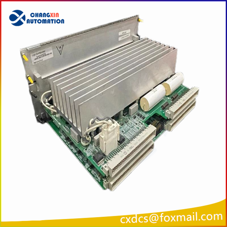
Model: IS215VCMIH2C (common suffixes A/CC are compatible with hardware pins)
system: GE Speedtronic Mark VI generator / turbine triple redundancy (TMR) control system
Product positioning: VME bus main communication interface board, serving as the core communication hub for CPU, local I/O, remote expansion rack, and IONet control network
Installation specifications: 6U VME C-size, occupying 2 VME slot positions, cabinet IP20 protection
Original manual number: GEH-6421 (Mark VI system hardware manual, factory only provides a simple safety card, no complete paper manual)
Product status:停产; market supply is brand new inventory, dismantled for inspection spare parts
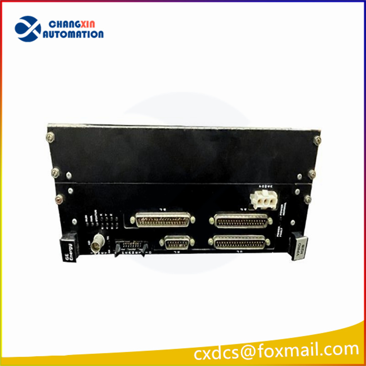
Front-end Hardware Interface Configuration
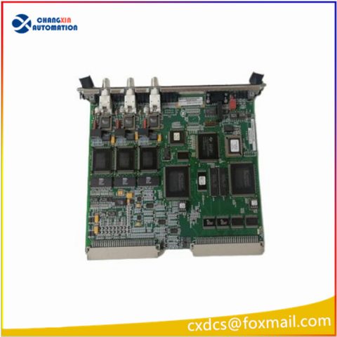
3 IONet 10Base2 coaxial BNC interfaces
System redundancy control network, 10Mbps bus, used for real-time data interaction between multiple controllers and expansion racks; each path has TX/RX/CD communication indicator lights
1 DB9 RS232 debugging serial port
Local console debugging, firmware upgrade, IP initialization, fault log reading, can be directly connected to notebook terminal
J3, J4 two 37-pin I/O expansion interfaces
Connect to the on-site terminal board, collect process switch quantity and analog signal
Hardware reset button + system status LED indicator group
Core Electrical Parameters
Power supply: VME backplane 5V/24VDC power supply, total machine power consumption approximately 25W
Processor: 32-bit DSP dedicated communication processing chip
Operating temperature: 0℃~+60℃; Storage temperature: -40℃~+85℃
Supported architecture: Triple redundancy TMR system, meeting the high reliability requirements of generator safety control
Bus standard: IEEE1014 VME industrial bus
Core Functions
VME bus data forwarding
Realize high-speed data interaction between CPU and all I/O cards of this rack, issue control instructions, upload collected parameters
IONet redundant networking communication
Through 3 coaxial buses connect multiple control racks and redundant controllers to achieve millisecond-level data synchronization and no-disruption primary-backup switching
Centralized collection and processing of on-site I/O signals
Integrate multiple DI/AI/DO signal acquisition circuits, collect generator speed, temperature, pressure, valve position, emergency stop interlock, etc.
Local maintenance diagnosis
RS232 serial port supports on-site fault troubleshooting, firmware flashing, event waveform reading, system parameter configuration
Hardware fault self-diagnosis
Real-time monitoring of VME bus, IONet link, backplane power supply, I/O circuit faults, report abnormalities through panel indicator lights
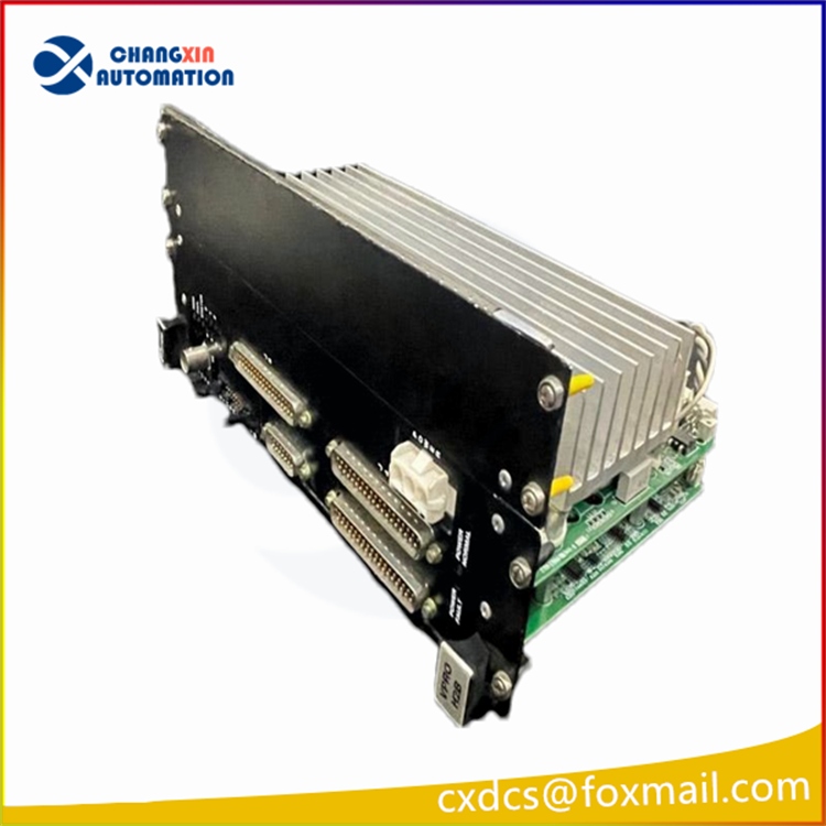
Panel Indicator Light Meanings (Quick Fault Troubleshooting)
RUN (operation light): Always on = module is running normally; Off = hardware has not started / firmware is abnormal
FAIL (fault light): Always on = module self-check failed, bus communication failure, TMR redundancy synchronization abnormal
STATUS (status light): Blinking = system is initializing; Always on = ready standby
1/2/4/8 lights: IONet network node address status indicator lights, used to identify bus node number
Each BNC port TX/RX/CD: TX data sending, RX data receiving, CD bus conflict detection
Typical Application Scenarios
GE 6FA, 9FA heavy-duty gas turbines, steam turbines Mark VI control system
Thermal power combined cycle power station, generator main control of self-owned power plants, FSSS furnace safety monitoring system Triple redundant safety control cabinet for large-scale oil and gas, refining and chemical turbine generators

There are no reviews yet.