


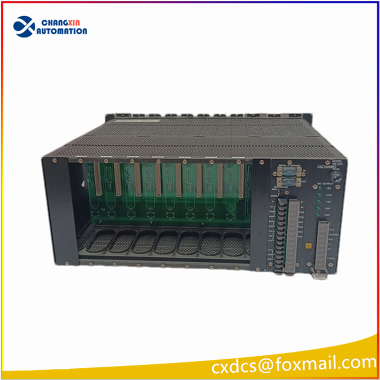
I. VM-5H3 (8-slot TSI System Rack)
Basic Parameters
Model: VM-5H3
Slot Specifications: Standard 8-slot 19-inch 3U rack, compatible with all VM-5 series monitoring cards (MP-2S, MP-2W2, VM-5K, etc.)
Installation Method: Cabinet embedded installation, front-mounted monitoring modules, rear-mounted power/communication accessories, all board cards support hot swapping
Power Supply Method: Requires VM-5Z series DC power module (installed at the rear of the rack), input AC 85~264V, output stable DC 24V for all slots
Environmental Parameters: Operating temperature 0℃~+65℃, IP20, CE, LR classification society certification, compliant with API 670 turbine TSI safety standards
Overall Size: 430mm (width) × 133mm (height) × 450mm (depth), approximately 6.5kg
Rack Configuration Rules
Among the 8 slots, one slot must be fixed to install VM-5P3, and the remaining 7 slots can be freely installed with vibration, displacement, axial displacement, etc. monitoring cards
Rack Backplane Built-in Parallel Bus, achieving data aggregation, power distribution, and centralized alarm signals
Can be paired with VM-5Y relay expansion module, VM-53 communication module to realize multi-rack networking, Modbus RTU remote transmission to DCS
Core Function
As the base of the entire TSI system, it uniformly supplies power to all monitoring cards, conducts bus data interaction, centrally collects axis vibration, displacement, speed, etc. measurement points, and uniformly outputs 4-20mA analog signals, relay alarm signals.
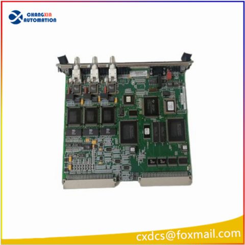
VM-5P3 (Phase Synchronization + System Communication Power Status Unit)
Basic Parameters
Installation Position: Exclusive fixed slot of VM-5H3 rack, only one can be installed per rack, cannot be used as a normal measurement point monitoring slot
Power Supply: DC 24V, overall power consumption approximately 20mA
Operating Temperature: 0℃~+65℃, three-proof industrial design
Two Core Functions
1. Dual-channel phase synchronization (rotor speed phase acquisition)
Connect magnetic-electric and eddy current phase synchronization probes, collect rotor speed and phase pulse signals
Output after shaping as standard pulse signals, provide speed reference for all vibration, displacement cards in the rack, used for vibration spectrum analysis, order analysis, eccentricity measurement
Can set pulse trigger level, hysteresis threshold, resist on-site interference to prevent erroneous counting
2. System centralized monitoring and communication aggregation
System power OK alarm contact: Real-time monitor rack power supply, backplane bus status, abnormal power output outputs passive dry contact alarm to DCS
Timing trigger, first fault reset: Provide global alarm reset terminal, one-click clear all module locked fault alarms of the entire rack
Bus Hub: Aggregate the operation, alarm, fault data of all 8 slot monitoring modules, provide a unified data interface for the upper-level communication module
Front panel two BNC buffer outputs: Can be used to extract the original waveforms of phase synchronization, for on-site oscilloscope debugging of the speed loop
Panel Indicators
PWR (green): Rack power supply normal
SEQUENCE (yellow): Timing enable
TRIGGER (yellow): Phase synchronization pulse normal acquisition
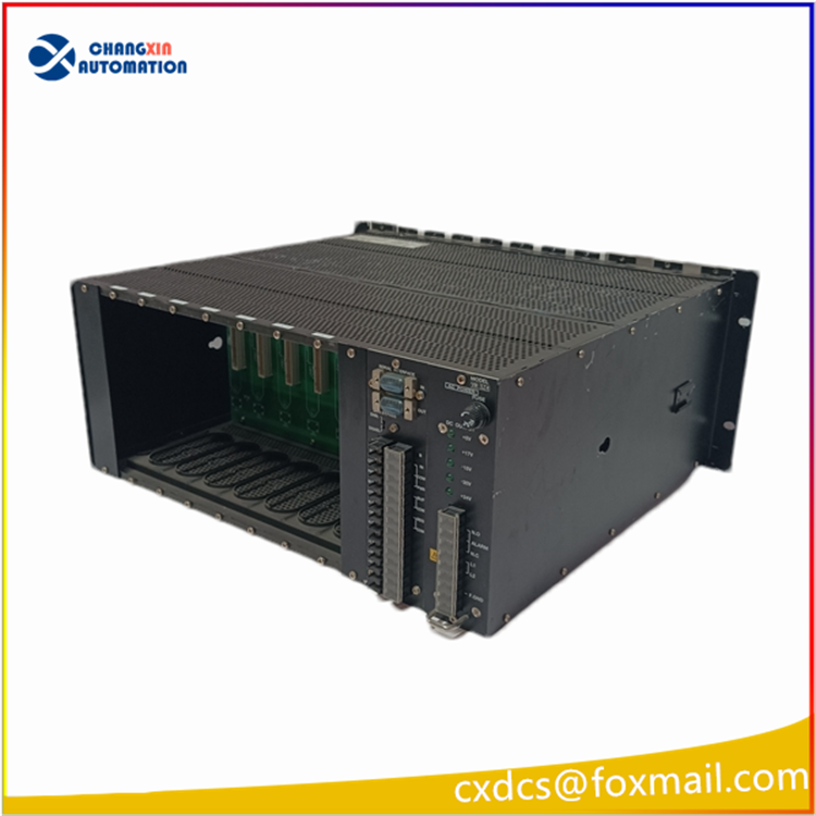
Standard Typical Configuration of VM-5H3 Complete Unit
1 x VM-5H3 8-slot rack
1 x VM-5P3 phase synchronization system unit (fixed slot)
1 x VM-5Z4 rack DC power module (rear-mounted)
Up to 7 pieces: MP-2S/MP-2W2/VM-5K vibration displacement monitoring cards
Optional: VM-53 dual-channel Modbus communication card (RS485), VM-5Y relay expansion card

There are no reviews yet.