

TOSHIBA USIO21 (Printed Wiring USIO21 / Housing Mark US1021) Module Detailed Explanation
I. Basic Identity
Brand: Toshiba (Japanese original factory)
Full Name: Universal Serial I/O (Universal Serial Interface for I/O) communication interface module, belongs to Toshiba V-Series / PROSEC DCS/PLC control system, has been discontinued, a large number of legacy power plants, nuclear power plants, paper mills, chemical plants projects are still in use
Front of the housing is printed US1021, the material model code is USIO21, the two are the same hardware, the label can be directly checked for the revision version (such as Rev: 1.C3.A1)
Position: Data transfer, protocol conversion, isolation communication card between the main control CPU and on-site serial peripheral devices (frequency converter, instrument, remote IO, third-party controller)
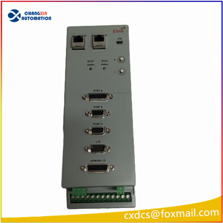
Hardware Interfaces and Panel Indicators
1. Power Supply Terminal (left AC-IN)
Power Supply Specifications: 100–240VAC wide-range AC power supply (L/N/FG grounding terminals), the cabinet is directly connected to the factory AC power supply, no additional DC power required
2. Status Indicators (PWR/ERR/RUN)
PWR: Power indicator, constantly on = Normal power supply
ERR: Fault indicator on = Communication abnormal / Configuration error / Hardware failure
RUN: Running flashing = Module program is running normally, data transmission is normal
3. DIP Switches
STN-H / STN-L / MODE two blue DIP switches: used for setting station address, communication rate, master-slave working mode
4. Communication Ports
DB9 serial port: RS232 debugging / programming port, used for downloading communication parameters, reading diagnostic logs
Two sets of fiber optic interfaces: used for internal fiber redundant bus communication, to build redundant control network
Green plug-in terminals: external serial I/O connection terminals, connected to RS422/RS485 field devices externally
Core Functions
Multi-protocol serial data collection and forwarding
Configurable RS232/RS422/RS485, compatible with Modbus RTU, custom serial protocol, upload on-site instruments, frequency converters, flow meters data to DCS main CPU, and simultaneously issue control instructions.
Electrical optical isolation
Built-in isolation at communication ports, blocking on-site interference, surges, avoiding interference breakdown of the main control CPU.
Redundant networking
Built-in fiber optic interfaces, support dual network redundancy, single link disconnection automatically switch, ensuring continuous communication for critical processes.
Local parameter storage
Communication baud rate, station number, protocol mapping parameters are saved even when power is off, and the module can be directly imported with the original configuration when replaced.
IV. Key Electrical & Environmental Parameters
Power Supply: AC 100–240V 50/60Hz
Operating Temperature: -20℃ ~ +60℃, suitable for long-term operation in control room cabinets
Isolation Voltage: High voltage isolation between serial ports and system buses
Structure: Metal housing with ventilation holes, resistant to vibration, electromagnetic interference, suitable for power plants / heavy industry environments
Origin: Produced in Japan
Typical Application Scenarios
Toshiba’s old DCS system, external connection of third-party intelligent instruments, electric actuators, frequency converter speed regulation devices
Access of serial data from auxiliary control of steam turbines in thermal power plants, water treatment systems to the upper control system
Expansion of serial IO channels for PROSEC PLC in old production lines of paper mills, metallurgy
Distributed remote serial data collection for SCADA system
Maintenance & Spare Parts Key Points
Life Cycle Status: The original factory has already been discontinued, the market circulation is mainly composed of disassembled test spare parts, refurbished parts, and inventory surplus goods; When purchasing, it is essential to verify the hardware Revision version. Different firmware versions are incompatible with each other.
Pre-replacement operations
Export the original communication configuration (baud rate, station address, protocol mapping table) through the DB9 debugging port
Record the original position of the jumpers, and the new machine’s jumpers must be exactly the same as the original machine
After replacement, check the status of the PWR/RUN lights, and verify whether the serial port data on the upper computer is refreshed normally
Common faults
Internal power supply aging: The PWR light does not light up when powering on, and the module cannot start
Fiber optic transceiver aging: Communication of redundant links is interrupted
RS485 driver chip damage: No data is uploaded from the on-site instrument, and the ERR indicator is constantly on and alarming
VII. Confusion and Distinction

There are no reviews yet.