

I. Basic Material Information
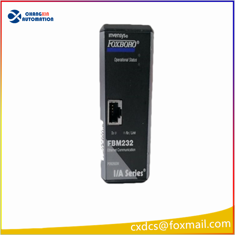
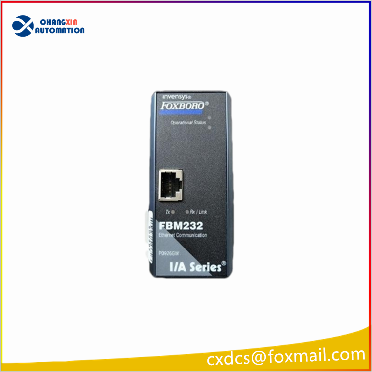
Model: FBM232
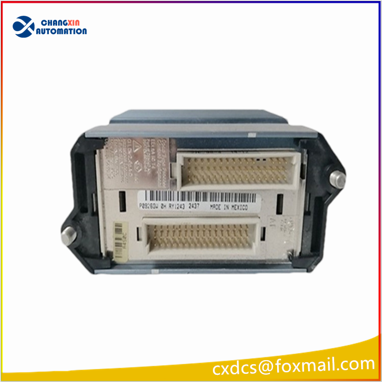
Original factory order number: P0926PW (The same series has a common suffix P0926GW, the hardware pins are fully compatible and can be directly interchanged)
Brand affiliation: Foxboro (now part of Schneider)
System: I/A Series, Foxboro Evo DCS control system
Module type: FDSI Field Device System Integrated Ethernet Communication Module
Installation method: FBM Field Remote Terminal Installation (local installation in the cabinet, not a control rack backplane card)
Original factory manual number: PSS 31H-2Z32 (English official user manual, only comes with a simple safety instruction page at factory)
Protection level: IP30, G3 industrial harsh environment level
Core Electrical Parameters
Power supply specification: DC24V (allowable range 21.6V~25.2V), maximum power consumption 7W
Network port specification: Single RJ45, 10/100Mbps Auto-Sensing Ethernet
Load capacity: A single module can connect up to 64 Ethernet field devices, and supports a maximum of 2000 DCI data points connection
Minimum data refresh cycle: 500ms
Operating environment: -40℃ ~ +70℃, no condensation, no corrosive gases
Weight: 284g
Support for Mainstream Communication Protocols
The module is a universal hardware platform, and through downloading the corresponding driver, multiple protocols can be accessed:
Modbus TCP (most commonly used: frequency converters, third-party PLCs, intelligent instruments, power meters)
Ethernet/IP, DNP3 TCP, IEC 60870-5-104
Supports automatic conversion of floating-point, 16/32-bit integer, and packaged switch quantity data formats
Core Functions
Third-party device gateway access
As a protocol gateway between DCS and external Ethernet devices, it collects data from frequency converters, third-party PLCs, online analyzers, intelligent meters, etc. and uploads it to the I/A control system, while sending control instructions.
Mass point collection
A single module can connect up to 64 field devices, and can integrate thousands of analog and switch quantity points, significantly simplifying on-site wiring and system expansion.
Protocol data automatic conversion
Converts private protocol data of third-party devices into DCS system standard DCI database format, and directly calls it in the upper-level interface, alarm, and trend.
Communication failure self-diagnosis
Real-time monitoring of network port links, device heartbeats, data anomalies, etc., and can report communication interruption, timeout, device offline, etc. faults alarms in the upper-level system.
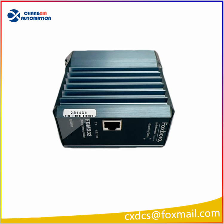
Panel Indicator Light Meanings
PWR: Power indicator, constantly on = 24V power supply is normal; off = power supply is abnormal
RUN: Operation indicator, constantly on = module firmware is running normally; flashing = initialization / firmware loading in progress
LINK/ACT: Network port link + data flashing light, constantly on indicates network cable link is connected, flashing indicates data is being sent and received
FAULT: Fault indicator, constantly on = communication abnormal, driver loading failure, hardware self-check error

There are no reviews yet.